
Resonic F 
Mobile high-end measurement method, even for voluminous and elastic test objects
The Resonic-F measurement system consists of a platform that carries the test object and a congruent support frame directly below it. This is why the Resonic-F measurement system never takes up more space than its platform and is around four times more compact than the Resonic-S system. The compact design leads to a convenient measurement of voluminous test objects and an optimal aptitude for mobile applications.
After the requested test object has been lifted onto the platform, it is set in motion by a manual push. Laser distance sensors then pick up the signals of the resulting free vibrations in all six degrees of freedom and send them to the Resonic software. Due to its low natural vibrations, the Resonic-F Technology achieves highly accurate measuring results for very elastic test objects, such as helicopters.
The Resonic 350F system,for example, is used within measurement services for test objects up to 450 kg and does not have any restrictions of size. Measurement systems for heavier test objects can easily be made in accordance with customer requirements. The Resonic-F technology is used for, among other things, complete vehicles including engine gear units and flying objects.
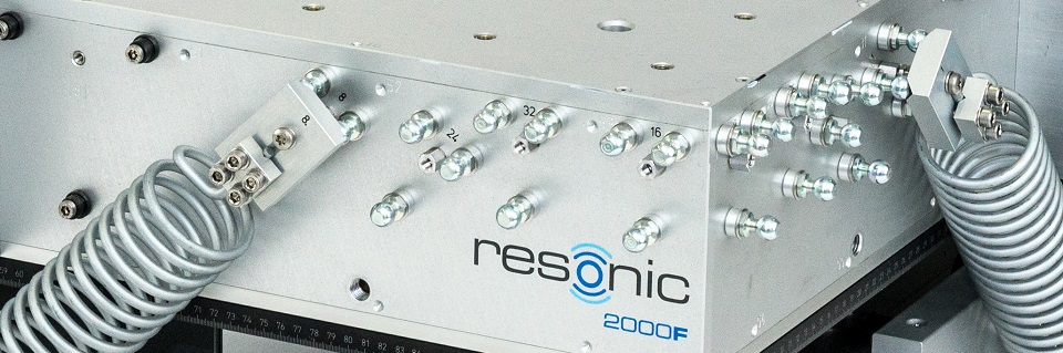
The platform and the support frame of the Resonic-F system are connected over spring packages and a bearing. This bearing consists of a plate with two knife-edge bearings that floats on three air bearings.
Two integrated machine levels and adjustable machine feet are intended to bring the platform in a horizontal position. Moveable steel cylinders adjust the platform inclination in such a way that it corresponds to the state in which the system was calibrated.
There is one horizontal spring on each of the six sides located between the uprights of the platform and those of the support frame. The minimum configuration of one vertical spring on three sides can be, depending on the mass of the test object, increased up to five with just a few quick motions.
Additionally, on three sides, there are always two laser distance sensors affixed underneath the platform, which measure the dynamic position of the platform in all five degrees of freedom.
Step 1 The test object is lifted onto the platform. Depending on the size and center of gravity height of the test object, vertical spring packages can be added or removed in order to achieve the perfect balance between the stability and low natural frequencies of the system.
Step 2 The platform inclination must be adjusted in such a way that it is consistent with the state of calibration. This happens via moveable steel cylinders inside the support frame.
Step 3 The test object is set in motions by a manual push. The resulting signals of free vibrations are picked up by laser distance sensors and sent to a PC through a USB-Interface.
Step 4 Based on the signals of free vibration, the Resonic software computes the complete inertia properties.


